Roller and guide materials matched to the web or filament
← TENSION SENSOR FAMILIES / TLC-WEB
Cantilever Web & Wire Tension Load Cells
Single-ended flange-mounted cantilever roll sensors for narrow webs, plus three-pulley geometries for wire, yarn and filament. Size for resultant roller force and the actual material path.
0.5–2,000 N FAMILY ENQUIRY SCOPEConfigure TLC-WEB & request quote →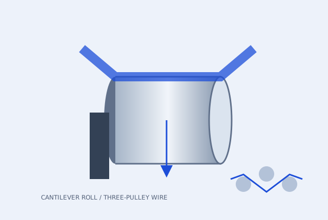
Single-ended flange or fixed three-pulley assembly
mV/V, 0–10 V or 4–20 mA signal chain
Cantilever roll enquiry range: 10–2,000 N. Three-pulley wire / fibre enquiry range: 0.5–500 N. Ceramic or hard-anodized guides depend on material and bending radius. This family covers single-ended cantilever and three-pulley installations. For PID control, confirm 0–10 V or 24 V PWM compatibility with the brake or servo input.
Ranges and options cover multiple configurations. A quotation confirms the capacity, material, thread, sealing, calibration and output of the selected unit.
CONFIGURATION AND DOCUMENT REVIEW
Compare the load path and signal before the drawing review
| Configuration reference | Force / use envelope | Signal request | Mechanical and evidence checks | Enquiry |
|---|---|---|---|---|
| TLC-WEB-CR Single-ended cantilever roll enquiry | 10–2,000N | 2.0 mV/V bridge / 4–20 mA / 0–10 V | Flange, roller length and applied moment Specify tare, speed, force direction and verified overload-stop details. Dimensions, accuracy and model datasheet: confirm on the approved configuration. | Request TLC-WEB-CR review → |
| TLC-WEB-3P Three-pulley wire / fibre enquiry | 0.5–500N; higher ranges by review | 2.0 mV/V bridge / 4–20 mA / 0–10 V | Guide groove / span / bending radius Requests up to 5,000 N need a separate assembly review. Confirm ceramic finish, friction and material bend limits. Dimensions, accuracy and model datasheet: confirm on the approved configuration. | Request TLC-WEB-3P review → |
Check guide surfaces and mechanical overload stops
For a cantilever roller, request the actual hard-stop geometry, permitted force/moment and recovery criteria after an overload event. For wire and fibre, confirm ceramic coating, groove geometry, guide span and bending radius. Neither a material name nor a requested overload multiple proves the assembly rating.
Review a digital web tension signal chain →BEFORE YOU SELECT CAPACITY
Calculate the load at the roller
- Send the minimum and maximum running tension, speed and web or wire dimensions.
- Draw incoming and outgoing material directions and define the deflection angle.
- Include roller weight, centre of gravity, cantilever moment and acceleration.
- Match controller bandwidth, brake or servo interface, supply and analogue scaling.
DESIGNED AROUND THE INSTALLATION
Where this geometry fits
- Battery separator and copper foil converting
- Label slitting and narrow-web printing
- Wire winding, carbon fibre and filament lines
CONFIGURE THE COMPLETE ASSEMBLY
Match the connection.
Protect the measurement.
A PID controller closes the loop only when its output, response rate and tuning match the brake, clutch or servo drive. Specify the complete control chain.
- Closed-loop PID web tension controller, interface matched
- Application-matched roller / ceramic wire guides
What to verify on the selected unit
Request a model drawing and pinout, the rated force and overload limits, calibration direction and test points, operating temperature, and model-specific environmental protection.
For digital configurations, confirm IODD / IO-Link implementation or the RS485 protocol and register map. For lifting or protective functions, establish the required certification and independent safety assessment before procurement.
Accessory prices, availability and lead time are confirmed with the configured quote.
WRAP GEOMETRY / FORCE SCREENING
Calculate roller force before choosing the range
F = 2 × T × sin(θ / 2)
θ is the change in material travel direction: 0° is straight through and 180° reverses direction. Incoming and outgoing tensions are equal; friction is neglected and the measuring axis follows the resultant.
The screening target multiplies this static force by your selected factor. The default 1.5 is a planning assumption, not a universal overload allowance or lifting design factor.
Include roller weight, cantilever moments, acceleration and actual support reactions in the final review. The indicated family envelope is not an approved nominal sensor rating.
Static resultant force
Force target to review: 212.132 N
Send these inputs for range review →Within the enquiry envelope of TLC-WEB-CR / TLC-WEB-3P. Confirm the actual nominal capacity and mounting.
ENGINEERING QUESTIONS / TLC-WEB
Does the sensor read web tension directly?
It measures the force component along its sensing axis. Convert that force using the wrap geometry, support arrangement and roller dead-weight tare.
Can I use the same setup for wire and wide web?
Guide geometry, bending radius, contact pressure, cantilever moment and measuring range differ. Submit the material path and dimensions to select the appropriate assembly.
Can you quote an existing-brand replacement?
Send the exact part number, drawing and calibration data. We compare dimensions, mechanical ratings and electrical interfaces before proposing a configuration. See the replacement checklist.
REPORT SCOPE / FIELD CHECKLIST
Know what a supplied report must contain
Preview the information to request before ordering. This is a blank field checklist, not an issued calibration certificate, proof-test result or laboratory accreditation.
Download open checklist PDF →Carry the interface and evidence into your RFQ
Open engineering notes →
Download the force-selection guide and editable interface worksheet.
Calibration and proof-load scope →Identify which report and accreditation scope the application requires.
Compare enquiry configurations →Filter the geometry, force envelope and signal before requesting a model.
CONFIGURATION / INTERFACE / DELIVERY
Send an engineering RFQ with the details intact
Choose the force path, signal and matching accessories. Include the destination so the quotation can confirm the product, calibration, freight and requested delivery term together.
[email protected]Open engineering notes are available in the downloads centre. Approved model STEP, IODD and real calibration reports are supplied against the selected configuration. Price, availability, lead time and warranty terms are confirmed in the formal quote.