17-4PH stainless or alloy steel options
← TENSION SENSOR FAMILIES / TLC-SBM
S-Beam Tension & Compression Load Cells
Axial force measurement for tensile test machines, suspended weighing and automated test fixtures. Start with the load case, then match the thread and signal chain.
5 N–20 t FAMILY ENQUIRY SCOPEConfigure TLC-SBM & request quote →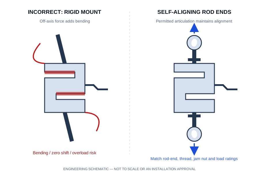
Metric M6–M36 or 1/4-28 to 1-1/4-12 UNF, by capacity
2.0 / 3.0 mV/V; conditioned output options
Low-force enquiry points: 5, 10, 20, 50, 100, 200 and 500 N. Industrial enquiry scope: 100 kgf–20 metric tonne-force; 200–40,000 lbf configurations require separate selection, not a point-for-point conversion. Metric M6–M36 and 1/4-28 through 1-1/4-12 UNF are model-dependent; nonstandard threads require a quantity and lead-time review.
Ranges and options cover multiple configurations. A quotation confirms the capacity, material, thread, sealing, calibration and output of the selected unit.
CONFIGURATION AND DOCUMENT REVIEW
Compare the load path and signal before the drawing review
| Configuration reference | Force / use envelope | Signal request | Mechanical and evidence checks | Enquiry |
|---|---|---|---|---|
| TLC-SBM-2MV 2.0 mV/V S-beam enquiry | 5N–20 metric tf across configurations | 2.0 mV/V bridge / 4–20 mA / 0–10 V / RS485 Modbus | Metric M6–M36, model dependent Confirm capacity-specific dimensions, thread depth, bridge resistance and calibration direction. Dimensions, accuracy and model datasheet: confirm on the approved configuration. | Request TLC-SBM-2MV review → |
| TLC-SBM-3MV 3.0 mV/V S-beam enquiry | 5N–20 metric tf across configurations | 3.0 mV/V bridge | UNF 1/4-28 through 1-1/4-12, model dependent Match sensitivity, excitation, wiring and complete thread callout before replacing a sensor. Dimensions, accuracy and model datasheet: confirm on the approved configuration. | Request TLC-SBM-3MV review → |
| TLC-SBM-UTM UTM / TEDS S-beam review | Application-specific force range | 2.0 mV/V bridge / 3.0 mV/V bridge / IEEE 1451.4 TEDS request | Fixture height / connector / thread review Request actual overload-stop travel/rating, connector pinout, TEDS support and separate directional calibration. Dimensions, accuracy and model datasheet: confirm on the approved configuration. | Request TLC-SBM-UTM review → |
BRIDGE SENSITIVITY / ELECTRICAL EXAMPLE
2.0 or 3.0 mV/V changes the amplifier span
Output sensitivity × excitation gives the ideal full-scale signal. The excitation here is an example, not the allowed supply rating of a selected sensor. Check bridge resistance, zero balance, wiring and amplifier range. A gain set for 3.0 mV/V will not automatically scale a 2.0 mV/V replacement correctly.
Request this bridge sensitivity →A similar diameter is not an interchangeable thread
| Callout example | Nominal diameter | Pitch | Drawing check |
|---|---|---|---|
| M6 × 1 | 6 mm | 1 mm | Confirm gender, tolerance, usable engagement depth, jam-nut clearance and installed height. |
| M12 × 1.75 | 12 mm | 1.75 mm | Confirm gender, tolerance, usable engagement depth, jam-nut clearance and installed height. |
| 1/4-28 UNF | 6.35 mm | 25.4 / 28 ≈ 0.907 mm | Confirm gender, tolerance, usable engagement depth, jam-nut clearance and installed height. |
| 1/2-20 UNF | 12.7 mm | 25.4 / 20 = 1.27 mm | Confirm gender, tolerance, usable engagement depth, jam-nut clearance and installed height. |
Thread examples explain why near-matching diameters cannot be substituted. Confirm the actual capacity-specific drawing; special pitches and larger interfaces require a separate manufacturing review.
BEFORE YOU SELECT CAPACITY
Keep side loads out of the measuring axis
- Specify tension, compression or calibrated bidirectional operation.
- Confirm thread diameter, pitch, engagement length and bearing centre distance.
- Select rated capacity above the actual peak load; account for acceleration and overload events.
- Request model-specific sealing, temperature, creep, non-linearity and calibration data.
DESIGNED AROUND THE INSTALLATION
Where this geometry fits
- Universal tensile testing machines
- Suspended hopper & tank scales
- Belt take-up and force-controlled fixtures
CONFIGURE THE COMPLETE ASSEMBLY
Match the connection.
Protect the measurement.
Spherical rod-end bearings accommodate permitted angular movement. Check load ratings, thread engagement, jam-nut torque and the sensor mounting instructions. They do not make every off-axis installation acceptable.
- Matched pair of spherical rod-end bearings + jam nuts
- Pair of forged eye bolts / clevis yoke forks
What to verify on the selected unit
Request a model drawing and pinout, the rated force and overload limits, calibration direction and test points, operating temperature, and model-specific environmental protection.
For digital configurations, confirm IODD / IO-Link implementation or the RS485 protocol and register map. For lifting or protective functions, establish the required certification and independent safety assessment before procurement.
Accessory prices, availability and lead time are confirmed with the configured quote.
WEB-ROLLER EQUATION REFERENCE
F = 2 × T × sin(θ / 2)
This equal-tension, frictionless web-roller relation uses travel-direction deflection θ. It is not a lifting rating or an installed wire-rope clamp calibration model. Roller weight, dynamic loads and support distribution are separate.
Review geometry, units and measurement limits →ENGINEERING QUESTIONS / TLC-SBM
Can one sensor measure tension and compression?
Specify bidirectional calibration, the required force range in each direction, and the zero and span behaviour. A tension-only calibration does not establish compression performance.
Will a UNF bearing fit a metric sensor?
No. Diameter and pitch must both match. Send the complete thread callout, mounting drawing and required engagement length for review.
Can you quote an existing-brand replacement?
Send the exact part number, drawing and calibration data. We compare dimensions, mechanical ratings and electrical interfaces before proposing a configuration. See the replacement checklist.
REPORT SCOPE / FIELD CHECKLIST
Know what a supplied report must contain
Preview the information to request before ordering. This is a blank field checklist, not an issued calibration certificate, proof-test result or laboratory accreditation.
Download open checklist PDF →Carry the interface and evidence into your RFQ
Open engineering notes →
Download the force-selection guide and editable interface worksheet.
Calibration and proof-load scope →Identify which report and accreditation scope the application requires.
Compare enquiry configurations →Filter the geometry, force envelope and signal before requesting a model.
CONFIGURATION / INTERFACE / DELIVERY
Send an engineering RFQ with the details intact
Choose the force path, signal and matching accessories. Include the destination so the quotation can confirm the product, calibration, freight and requested delivery term together.
[email protected]Open engineering notes are available in the downloads centre. Approved model STEP, IODD and real calibration reports are supplied against the selected configuration. Price, availability, lead time and warranty terms are confirmed in the formal quote.