Define the force path, reduce side loads and use the correct wrap-angle equation for web and wire tension measurement.
Measure along the axis, without adding bending
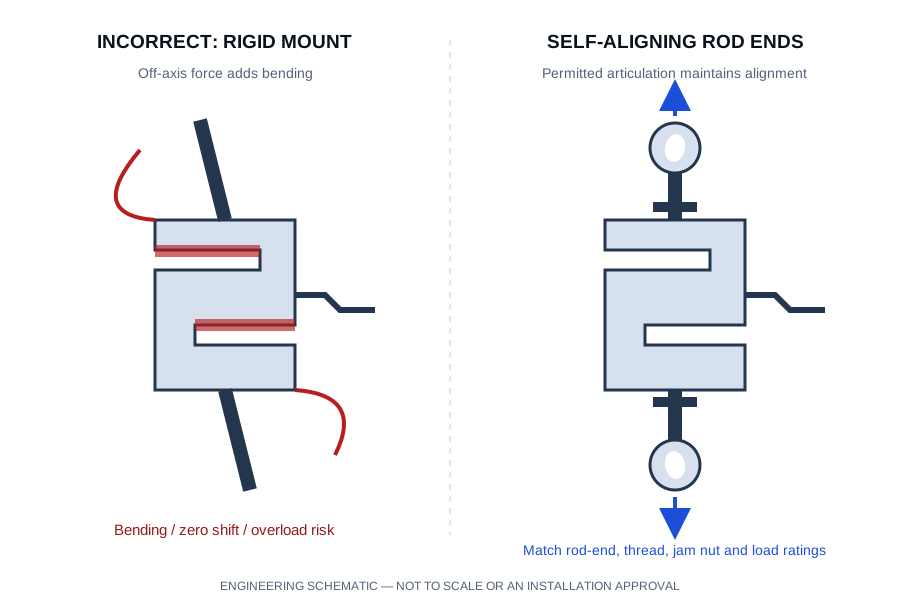
An S-beam load cell converts elastic strain into a bridge signal. A valid axial reading depends on how force enters the sensing body. A rigid, misaligned attachment can add bending moments that affect the reading and may exceed allowable loads.
Use model-approved spherical rod ends or clevis arrangements where appropriate. Keep the fixture aligned, avoid twisting the sensor during assembly, and respect engagement length and installation torque.
Rod ends and eye bolts are different components. Use only correctly rated hardware for the loading direction and do not assume an unqualified eye bolt is suitable for lifting.
SELF-ALIGNING LOAD PATH / SCHEMATIC, NOT TO SCALE
Define force units before comparing capacities
1 lbf ≈ 4.44822 N. At standard gravity, 1 kgf = 9.80665 N and 1 metric tonne-force = 9.80665 kN. Mass in kg or tonnes is not force; dynamic acceleration changes the force experienced by the sensor.
WRAP GEOMETRY / FORCE SCREENING
Calculate roller force before choosing the range
F = 2 × T × sin(θ / 2)
θ is the change in material travel direction: 0° is straight through and 180° reverses direction. Incoming and outgoing tensions are equal; friction is neglected and the measuring axis follows the resultant.
The screening target multiplies this static force by your selected factor. The default 1.5 is a planning assumption, not a universal overload allowance or lifting design factor.
Include roller weight, cantilever moments, acceleration and actual support reactions in the final review. The indicated family envelope is not an approved nominal sensor rating.
Static resultant force
Force target to review: 212.132 N
Within the enquiry envelope of TLC-WEB-CR / TLC-WEB-3P. Confirm the actual nominal capacity and mounting.
For equal tensions of 100 N and a 90° change in travel direction, the ideal resultant is 141.42 N. At 180°, it is 200 N. If the web follows a straight path with no deflection, the ideal tension resultant approaches zero. Real bearing friction, roller weight and acceleration need separate treatment.
Six-wire sense feedback addresses excitation lead drop
In a four-wire bridge connection, voltage lost along excitation conductors can change the voltage at the bridge. A compatible six-wire system senses excitation at the sensor and allows the instrument to compensate according to its design. Sense leads are feedback inputs, not additional force outputs.
Check the instrument's remote-sense support, maximum cable resistance and exact pinout. Follow the actual manufacturer wiring instructions; do not guess connections from cable colour.
Use the dynamic factor as an assumption to review
A screening factor such as 1.25 or 1.5 scales the ideal static calculation. It does not replace measured transients, roller tare, cantilever moments, fatigue requirements or the device's own allowable overload. A two-support roller also requires its actual reaction distribution. Record these unknowns in the RFQ.
Calibrate the assembled signal chain
Inspect mounting and cable routing; prevent cable pull from adding unwanted forces.
Warm up the electronics and tare at the installed orientation.
Apply traceable reference loads across the actual operating range and directions.
Check zero return, repeatability, hysteresis and controller scaling.
Record the final setup, units, calibration date and acceptance criteria.
References explain general measurement principles; their ratings do not establish TLC product performance. Engineering guide reviewed 11 November 2026.
Choose the force path, signal and matching accessories. Include the destination so the quotation can confirm the product, calibration, freight and requested delivery term together.
Open engineering notes are available in the downloads centre. Approved model STEP, IODD and real calibration reports are supplied against the selected configuration. Price, availability, lead time and warranty terms are confirmed in the formal quote.