TLC SENSOR SELECTION
Four geometries.
One clear load path.
Compare the measurement arrangement first. Capacity, threads, sealing, calibration and output are confirmed for the selected model.
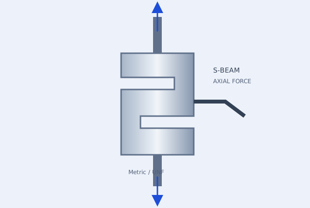 01 / TLC-SBM
S-Beam Tension & Compression Load Cells
Axial force measurement for tensile test machines, suspended weighing and automated test fixtures. Start with the load case, then match the thread and signal chain.
Explore TLC-SBM →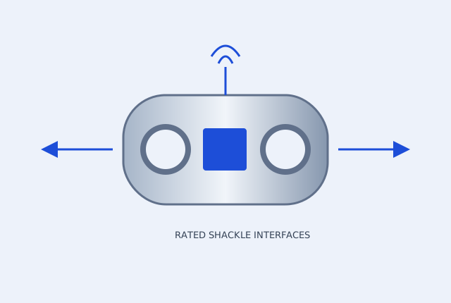 02 / TLC-LNK
Wireless & Cabled Tension Load Links
Configure a load link for crane proof-load testing, water-bag trials, mooring or suspended load monitoring. Match the complete load path, shackles and readout before ordering.
Explore TLC-LNK →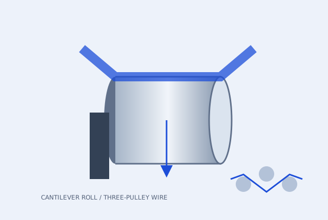 03 / TLC-WEB
Cantilever Web & Wire Tension Load Cells
Single-ended flange-mounted cantilever roll sensors for narrow webs, plus three-pulley geometries for wire, yarn and filament. Size for resultant roller force and the actual material path.
Explore TLC-WEB →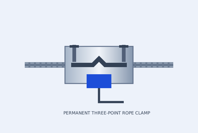 04 / TLC-ROP
Permanent Wire Rope Clamp & Chain Tension Measurement
Permanently installed rope clamp sensing for running-load monitoring, overload indication and slack-rope detection. Chain measurements require a separately rated chain-compatible assembly.
Explore TLC-ROP →CONFIGURATION ENQUIRY CATALOGUE
Filter by force, geometry and signal
These configuration references organise an engineering enquiry. Listed envelopes describe the scope to discuss across variants; exact capacity, dimensions, availability and approvals are confirmed on the model documentation.
| Configuration / use | Force enquiry envelope | Signal requests | Interface review | Next step |
|---|---|---|---|---|
| TLC-SBM-2MV 2.0 mV/V S-beam enquiry | 5N–20 metric tf across configurations | 2.0 mV/V bridge / 4–20 mA / 0–10 V / RS485 Modbus | Metric M6–M36, model dependent Confirm capacity-specific dimensions, thread depth, bridge resistance and calibration direction. | Review this configuration → |
| TLC-SBM-3MV 3.0 mV/V S-beam enquiry | 5N–20 metric tf across configurations | 3.0 mV/V bridge | UNF 1/4-28 through 1-1/4-12, model dependent Match sensitivity, excitation, wiring and complete thread callout before replacing a sensor. | Review this configuration → |
| TLC-SBM-UTM UTM / TEDS S-beam review | Application-specific force range | 2.0 mV/V bridge / 3.0 mV/V bridge / IEEE 1451.4 TEDS request | Fixture height / connector / thread review Request actual overload-stop travel/rating, connector pinout, TEDS support and separate directional calibration. | Review this configuration → |
| TLC-SBM-IOL Smart S-beam configuration | Force range confirmed by model | M12 IO-Link | M12 device / cable transmitter configuration Confirm integrated versus external electronics, IODD, process data, supply and master cycle time. | Review this configuration → |
| TLC-WEB-IOL Smart cantilever tension configuration | Roller force confirmed by geometry | M12 IO-Link | Single-ended flange + M12 signal chain Confirm force direction, controller scaling and IODD for the actual transmitter. | Review this configuration → |
| TLC-LNK-CBL Cabled proof-load link enquiry | 1–500 metric tf across configurations | 2.0 mV/V bridge / 4–20 mA / RS485 Modbus | Shackle pin / jaw clearance by approved drawing Working load, proof-load target and minimum breaking-load evidence are separate requirements. | Review this configuration → |
| TLC-LNK-WLS Wireless load-link enquiry | 1–500 metric tf across configurations | Wireless handheld kit | Matched rated shackle assembly Confirm region, readout protocol, update rate, battery and signal-loss behaviour. | Review this configuration → |
| TLC-HOK Integrated hook load-path review | 1–30 metric tf requested scope | Wireless handheld kit / 4–20 mA | Hook swivel / latch / overhead clearance A dedicated hook assembly requires its own rated load path and approval; not a link accessory assumption. | Review this configuration → |
| TLC-WTSTL Stainless marine link review | 5–100 metric tf requested scope | Wireless handheld kit / 4–20 mA / RS485 Modbus | Shackle interfaces and material/environment review Confirm 316L material, sealing, immersion conditions and antenna location; do not assume radio transmission through water. | Review this configuration → |
| TLC-LNK-STG Low-visibility stage link review | 0.5–5 metric tf requested scope | Wireless handheld kit | Suspension geometry / finish review Specify required minimum breaking load, finish and applicable approvals; a reduced WLL is not certification. | Review this configuration → |
| TLC-HTL Hollow-anchor tensioning review | 100–2,000kN requested scope | 4–20 mA / 2.0 mV/V bridge | Bore / seating / distribution plate review Identify whether force is inferred from hydraulic pressure or measured by an annular strain-gauge element. | Review this configuration → |
| TLC-WEB-CR Single-ended cantilever roll enquiry | 10–2,000N | 2.0 mV/V bridge / 4–20 mA / 0–10 V | Flange, roller length and applied moment Specify tare, speed, force direction and verified overload-stop details. | Review this configuration → |
| TLC-WEB-3P Three-pulley wire / fibre enquiry | 0.5–500N; higher ranges by review | 2.0 mV/V bridge / 4–20 mA / 0–10 V | Guide groove / span / bending radius Requests up to 5,000 N need a separate assembly review. Confirm ceramic finish, friction and material bend limits. | Review this configuration → |
| TLC-ROP Permanent rope clamp enquiry | Ø6–52 mm; force up to 30 metric tf by review | 4–20 mA | Rope construction / straight length / clamp geometry Calibrate on the installed rope; the rope diameter alone does not establish the force range. | Review this configuration → |
| TLC-CHN Dedicated chain force review | Chain grade and load path specific | 4–20 mA / 2.0 mV/V bridge | BL534 / BL634 leaf chain or lifting-link details Never clamp a rope fixture onto chain. Submit pitch, plate/pin dimensions, grade and required rating. | Review this configuration → |
| TLC-CTL-PID Closed-loop PID controller review | Sensor and drive dependent | Closed-loop PID controller | Panel / rail mounting and drive interface Match sensor input, feedback scaling,0–10V/PWM output, line speed and tuning. | Review this configuration → |
| TLC-CTL-M12 M12 IO-Link bridge transmitter | Bridge excitation and input dependent | M12 IO-Link | M12 pinout / supply / cable routing Request IODD, bridge supply, resolution, process data and actual cycle-time limits. | Review this configuration → |
| TLC-CTL-DIN DIN-rail bridge transmitter | Bridge input dependent | 4–20 mA / 0–10 V / RS485 Modbus | Rail / shielding / PLC input Confirm bridge sensitivity, gain range, address/register map and fault current. | Review this configuration → |
| TLC-CTL-WLS Wireless peak-hold readout | Paired radio system dependent | Wireless handheld kit | Readout, receiver and transmitter protocol Confirm compatible transmitter, peak capture rate, communication-loss response and battery. | Review this configuration → |
Carry the interface and evidence into your RFQ
Download the force-selection guide and editable interface worksheet.
Calibration and proof-load scope →Identify which report and accreditation scope the application requires.
Compare enquiry configurations →Filter the geometry, force envelope and signal before requesting a model.
CONFIGURATION / INTERFACE / DELIVERY
Send an engineering RFQ with the details intact
Choose the force path, signal and matching accessories. Include the destination so the quotation can confirm the product, calibration, freight and requested delivery term together.
[email protected]Open engineering notes are available in the downloads centre. Approved model STEP, IODD and real calibration reports are supplied against the selected configuration. Price, availability, lead time and warranty terms are confirmed in the formal quote.