Rope-specific clamp and contact surfaces
← TENSION SENSOR FAMILIES / TLC-ROP
Permanent Wire Rope Clamp & Chain Tension Measurement
Permanently installed rope clamp sensing for running-load monitoring, overload indication and slack-rope detection. Chain measurements require a separately rated chain-compatible assembly.
Ø6–52 mm FAMILY ENQUIRY SCOPEConfigure TLC-ROP & request quote →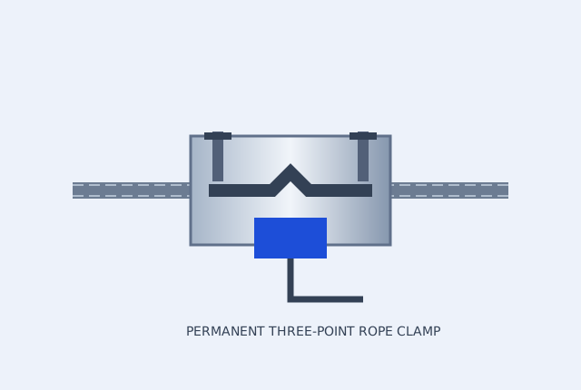
Industrial force measurement and monitoring only. Use as a primary safety cutoff for passenger lifting, elevators or overhead lifting requires a separately specified, approved safety system and written application-specific certification.
Three-point fixed clamp; rope construction and diameter matched
4–20 mA and alarm interface options
Permanent wire rope clamp enquiry scope: Ø6–52 mm rope and up to 30 metric tonne-force, subject to rope-specific evaluation. Select 4–20 mA and overload / slack-rope relay interfaces as required. Do not install a wire-rope clamp on chain: chain tension requires a dedicated rated load path and separate sensor selection.
Ranges and options cover multiple configurations. A quotation confirms the capacity, material, thread, sealing, calibration and output of the selected unit.
CONFIGURATION AND DOCUMENT REVIEW
Compare the load path and signal before the drawing review
| Configuration reference | Force / use envelope | Signal request | Mechanical and evidence checks | Enquiry |
|---|---|---|---|---|
| TLC-ROP Permanent rope clamp enquiry | Ø6–52 mm; force up to 30 metric tf by review | 4–20 mA | Rope construction / straight length / clamp geometry Calibrate on the installed rope; the rope diameter alone does not establish the force range. Dimensions, accuracy and model datasheet: confirm on the approved configuration. | Request TLC-ROP review → |
| TLC-CHN Dedicated chain force review | Chain grade and load path specific | 4–20 mA / 2.0 mV/V bridge | BL534 / BL634 leaf chain or lifting-link details Never clamp a rope fixture onto chain. Submit pitch, plate/pin dimensions, grade and required rating. Dimensions, accuracy and model datasheet: confirm on the approved configuration. | Request TLC-CHN review → |
Three stages of permanent-rope commissioning
1 / Survey the rope
Identify diameter, strand/core construction, load range, accessible straight length and the machine's permitted installation procedure.
2 / Fit the approved clamp
A qualified installer follows the actual model instructions and specified fastener torque. Do not infer installation dimensions or torque from this schematic.
3 / Calibrate and test alarms
Use representative installed-rope loads, verify scaling and test the independently assessed overload/slack-rope control response.
Leaf chain requires its own plate and pin geometry
| Chain identification | Dimensions and evidence to request |
|---|---|
| BL534 / BL634 leaf-chain enquiry | Actual pitch, plate arrangement, pin diameter, plate thickness, manufacturer drawing and rated load. |
| Lifting-link chain enquiry | Chain grade, link dimensions, connector geometry, permitted loading and dedicated sensor assembly approval. |
A rope-clamp drawing cannot establish a chain fixture. TLC-CHN requests are evaluated separately; the chain reference alone is not a dimensional approval.
BEFORE YOU SELECT CAPACITY
Match the clamp to the installed rope
- State rope diameter, construction, core, surface condition and expected tension.
- Confirm the permanent installation location, available straight length and access.
- Calibrate on the installed rope under representative conditions.
- Define alarm thresholds and an independently assessed safety control architecture.
DESIGNED AROUND THE INSTALLATION
Where this geometry fits
- Crane dead-end overload monitoring
- Elevator multi-rope load balancing
- Mine hoist rope monitoring retrofits
CONFIGURE THE COMPLETE ASSEMBLY
Match the connection.
Protect the measurement.
Permanent clamp measurement depends on the rope construction and installed geometry. Include commissioning calibration and the required alarm interface in the enquiry.
- Overload / slack-rope alarm interface module
- Installed-rope calibration support
What to verify on the selected unit
Request a model drawing and pinout, the rated force and overload limits, calibration direction and test points, operating temperature, and model-specific environmental protection.
For digital configurations, confirm IODD / IO-Link implementation or the RS485 protocol and register map. For lifting or protective functions, establish the required certification and independent safety assessment before procurement.
Accessory prices, availability and lead time are confirmed with the configured quote.
WEB-ROLLER EQUATION REFERENCE
F = 2 × T × sin(θ / 2)
This equal-tension, frictionless web-roller relation uses travel-direction deflection θ. It is not a lifting rating or an installed wire-rope clamp calibration model. Roller weight, dynamic loads and support distribution are separate.
Review geometry, units and measurement limits →ENGINEERING QUESTIONS / TLC-ROP
Can a rope clamp be used on chain?
A wire-rope clamp is not a chain fixture. Chain pitch, link grade and load path require a dedicated rated design. Submit chain details for feasibility review.
Can the clamp be installed without cutting the rope?
A compatible clamp can be fitted around an accessible straight rope section. Installation suitability and calibration must be confirmed for that rope and machine.
Can you quote an existing-brand replacement?
Send the exact part number, drawing and calibration data. We compare dimensions, mechanical ratings and electrical interfaces before proposing a configuration. See the replacement checklist.
REPORT SCOPE / FIELD CHECKLIST
Know what a supplied report must contain
Preview the information to request before ordering. This is a blank field checklist, not an issued calibration certificate, proof-test result or laboratory accreditation.
Download open checklist PDF →Carry the interface and evidence into your RFQ
Open engineering notes →
Download the force-selection guide and editable interface worksheet.
Calibration and proof-load scope →Identify which report and accreditation scope the application requires.
Compare enquiry configurations →Filter the geometry, force envelope and signal before requesting a model.
CONFIGURATION / INTERFACE / DELIVERY
Send an engineering RFQ with the details intact
Choose the force path, signal and matching accessories. Include the destination so the quotation can confirm the product, calibration, freight and requested delivery term together.
[email protected]Open engineering notes are available in the downloads centre. Approved model STEP, IODD and real calibration reports are supplied against the selected configuration. Price, availability, lead time and warranty terms are confirmed in the formal quote.