Mechanical sensor
Confirm capacity, loading direction, thread or flange, overload limits and calibration.
APPLICATION / INTERFACE / EVIDENCE
Specify the force transducer, M12 connection and IO-Link device data together. Compare S-beam and cantilever signal chains before choosing integrated or cable-mounted electronics.
Review the configuration and documents →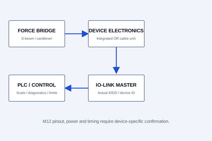
Confirm capacity, loading direction, thread or flange, overload limits and calibration.
Confirm bridge excitation, input span, supply, converter noise and engineering-unit scaling.
Confirm the exact IODD/device revision, port mode, process-data layout, diagnostics and update timing.
TLC-SBM-IOL and TLC-WEB-IOL organise requests for digital force measurement. A native sensor interface and a separately calibrated bridge transmitter are different configurations. Request a drawing showing where the electronics are installed and which assembly the calibration covers.
| Commissioning input | What to confirm |
|---|---|
| M12 connector | Pin assignment, supply limits, grounding and connector coding for the agreed device. |
| IODD and process data | Vendor/device identifiers, revision, force units, sign, resolution and diagnostic values. |
| Update timing | Device and master cycle time, filtering and complete PLC-loop delay; ADC resolution alone is not system accuracy. |
| Belt tension automation | Actual force path, mechanical travel, tension setpoint, actuator limits and a separately assessed protective function. |
Send your Siemens, Beckhoff or other master reference with the force range. A connector marked M12 does not by itself establish IO-Link compatibility.
Compare analogue, RS485 and IO-Link signal chains →CONFIGURATION AND DOCUMENT REVIEW
| Configuration reference | Force / use envelope | Signal request | Mechanical and evidence checks | Enquiry |
|---|---|---|---|---|
| TLC-SBM-IOL Smart S-beam configuration | Force range confirmed by model | M12 IO-Link | M12 device / cable transmitter configuration Confirm integrated versus external electronics, IODD, process data, supply and master cycle time. Dimensions, accuracy and model datasheet: confirm on the approved configuration. | Request TLC-SBM-IOL review → |
| TLC-WEB-IOL Smart cantilever tension configuration | Roller force confirmed by geometry | M12 IO-Link | Single-ended flange + M12 signal chain Confirm force direction, controller scaling and IODD for the actual transmitter. Dimensions, accuracy and model datasheet: confirm on the approved configuration. | Request TLC-WEB-IOL review → |
No. The strain-gauge bridge needs electronics that excite and digitise the signal. Confirm whether those electronics are integrated in the sensor, installed in the cable or supplied as a separate transmitter.
An IODD belongs to a specific IO-Link device and revision. Request the file for the agreed transmitter; generic device files are not interchangeable.
Download the force-selection guide and editable interface worksheet.
Calibration and proof-load scope →Identify which report and accreditation scope the application requires.
Compare enquiry configurations →Filter the geometry, force envelope and signal before requesting a model.
Replacing an existing sensor? Start with the sourced manufacturer reference and document checklist →
CONFIGURATION / INTERFACE / DELIVERY
Choose the force path, signal and matching accessories. Include the destination so the quotation can confirm the product, calibration, freight and requested delivery term together.
[email protected]Open engineering notes are available in the downloads centre. Approved model STEP, IODD and real calibration reports are supplied against the selected configuration. Price, availability, lead time and warranty terms are confirmed in the formal quote.